Advantages of automatic license plate recognition system

ANPR (Automatic Number-Plate Recognition) is a technology that uses optical character recognition on images to scan vehicle registration plates. ANPR can be used to save the images captured by the cameras as well as the text from the license plate.

Automatic number plate recognition is generally used by police forces throughout the world for law fulfillment basis, including to check if a vehicle is registered or licensed. It is also used for electronic toll collection on pay-per-use roads and as a method of indexing the activity of traffic for example by highways agencies.

Systems generally uses infrared lighting to permit the camera to capture the picture at any time of the day. Automatic number plate recognition technology must take into account plate differences from place to place.

Generally, some of the vehicle registration plate’s arrangements use variations in font sizes and places. ALPR camera solutions must be capable enough to deal with such differences in order to be truly powerful. More confused systems can deal with international differences, though many programs are individually modified to each country.

The cameras used in Automatic number plate recognition systems that can be closed-circuit television cameras, as well as mobile units, which are generally fixed to vehicles. Some systems use infrared cameras to take a high-quality image of the plates.

Automatic number plate recognition system’s software runs on quality computer hardware and can be connected to other applications or databases.

ANPR camera solution follows two basic approaches:

• Allows for the whole process to be performed at the site in real-time
• Other transmits all the images from many lanes to a remote computer location to perform the OCR process.

The data captured from the Vehicle plate like alphanumeric, date-time, lane identification, etc. is completed in approximately 250 milliseconds. This data can easily be transferred to a far computer for further processing if required.

In the other sequence, there are commonly large numbers of PCs used in a server station to manage high workloads. In such systems, there is a need to forward images to the remote server, and this can require larger bandwidth transmission media.

Many countries now started using license plates that are retroreflective. This returns reflected light back to the source and thus enhances the quality of the image. This is only achievable on committed automatic license plate recognition cameras.

Benefits:

• Automatic number plate recognition cameras are used to measure the average vehicle speed over longer distances
• Used to identify a motorist when he/she drives away without paying for their fuel
• Targeted advertisement
• Automatic number plate recognition cameras are used for Traffic management systems.
• Used to Analyze the behavior (route choice, origin-destination, etc.) of a motorist for transport planning purposes
• ANPR camera solutions automatically recognize customers based on their license plate and provide them the complete information about the items that they ordered the last time they used the service.
• Automatic license plate recognition camera solutions are used to recognize the guest vehicles in order to assist visitor management systems.

CAN ANPR CAMERAS BE DISCREETLY HIDDEN

On the roof or inside the vehicle? Both options of the ANPR camera placement have their pros and cons.

When it comes to innovation, in many countries police tend to be the followers rather than the pioneers. However, in recent years we have seen a remarkable increase of digitalization in law enforcement. One of the most evident examples of the ever-increasing use of technology by the police is vehicles fitted with roof cameras, the numbers of which have been growing throughout Europe.

Automatic Number (License) Plate Reading (ANPR or ALPR) cameras, able to recognize number plates of passing vehicles, have proven to be one of the most useful modern technologies, helping to clarify car thefts and other crimes.

Technical limitations

The technology consists of two parts. The first is a camera fitted with an infrared illuminator to improve visibility at twilight and night, and the second is a software capable of “reading” the number of plates from the captured image.

Conventional ANPR cameras are manufactured with an integrated infrared (IR) light.  They have almost exclusively been installed on car roofs.  If mounted inside the vehicle interior, a large part of the light spectrum is reflected or absorbed by the thermal glass.

However, apart from technical difficulties, some police representatives would appreciate, for various reasons, if the ANPR system could be installed inside the car interior. Some are concerned that the camera may get damaged or dirty, and others would like to also equip unmarked vehicles with the technology.

In the interior with no compromise

MOSY always listens to customer requirements and analyses how it can customize its solutions to meet specific needs. That is why MOSY responded to its clients’ desires and extended its portfolio to include an ANPR system that can be built into a police car interior.

The principle of the solution is that the infrared illumination is separated from the actual camera. In this case, the light-emitting diodes are fitted to the front end of the vehicle, thus avoiding undesired reflection or absorption of a part of the light spectrum. This allows the ANPR camera to be placed in the vehicle interior without compromising the accuracy of the number plate recognition compared to exterior camera solutions. This also eliminates any concerns about the potential effects of IR radiation on human health.

Solutions based on needs and desires

Of course, installation inside the car is more discreet and the hardware is better protected against possible mechanical damage and exposure to the elements. On the other hand, it also has its limits. Although in terms of license plate recognition accuracy, it is a fully adequate alternative to exterior ANPRs, it is not suitable for all scenarios.

For example, if there is a need to use the camera system to scan both sides of the road, or possibly all around the police vehicle, which is useful, for instance, when checking vehicles at car parks. In such cases, the installation of the interior solution is problematic due to limited options for the IR illumination and side cameras positioning.

The interior ANPR is therefore not a substitute, but rather an alternative to traditional exterior camera systems.
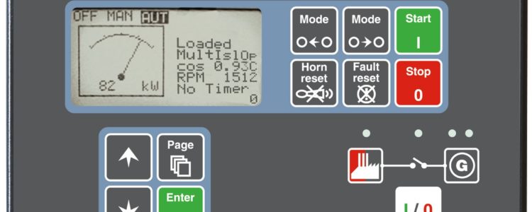
Single or multiple genset controllers

IPU carry a wide range of single or multiple genset controllers, for gensets operating in standby or parallel modes.


This advanced range of controls has been designed to simplify the installation, configuration and management of these complex applications.

Controllers available for both single and multiple genset applications include:

  • InteliCompact MINT – This controller is designed for single or multiple genset applications, which require automatic mains failure along, paralleling and load sharing functions.
  • ComAp InteliCompact SPtM – Compact genset controller for single genset operating in parallel to mains mode or Auto Mains Failure (AMF) mode with no-break transfers.
  • InteliGenNT – Gen-set controller for single or multiple generating sets operating in standby or parallel modes.
  • InteliGenNTC BaseBox – InteliGen NTC BaseBox is a comprehensive gen-set controller with detachable modular construction for both single and multiple gensets.
  • InteliSys NTC BaseBox – Premium gen-set controller for both single and multiple gensets operating in standby or parallel modes.

These controllers have many standard features, including built-in synchroniser and digital isochronous load-sharer which allow a total integrated solution for gensets in standby, island parallel or main parallel applications. These controllers are also able to control up to 32 gensets.

What are some of the benefits of single or multiple genset controllers?

  • Support of engines with ECU (Electronic Control Unit).
  • Excellent configurability to match customers needs.
  • Many communication options available for easy remote monitoring.
  • Built-in PLC functions.

To learn more on the benefits of specific controllers, head to product pages found below.

So, what are the benefits of running multiple gensets in parallel?

If space and capital is available, running multiple gensets is an attractive option.

In standby applications, the reliability of power supplies are critical. This is certainly the case in applications such as hospitals, bank and data centres. A multiple genset setup will help to ensure critical loads can be supported when combined with controllers from ComAp and Datakom. They allow for automatic adjustments for variations in load are able to make sure that a minimum number of gensets is online to serve the load.

A multiple genset setup can also make the task of scheduling maintenance simpler. As the risk of interrupting power supply is removed, regular maintenance can take place. This reduces the risk of power failure due to poorly maintained equipment.

A standby power system with multiple generator sets offers operating flexibility that can increase reliability, improve equipment longevity as well as reduce operating costs.


See the full range here:

Related Products

With AirTouch, Alexa has a new Skill to control your home climate.

Already love Alexa on the Amazon Echo speaker? Now, Alexa can control your air conditioning. With ducted reverse cycle systems, you can now use Amazon Alexa in conjunction with AirTouch to cool you down, warm you up, and more.

Using Alexa is as simple as asking a question – just ask, and Alexa will respond instantly from your Amazon Echo speaker.

airtouch and alexa

“Alexa, Turn on the Air Conditioning.”

“Alexa, What is the temperature of the kids room?*”

“Alexa, Set the family room to 22 degrees.*”

We believe that truly smart home automation technologies should make life easier and more comfortable, going beyond being pieces of technology.

Setting up the Skill with your Amazon account is easy. Watch our setup video to see how it is done using the app with your choice of Amazon Echo Speaker and AirTouch.

Download setup instructions for AirTouch 3 or AirTouch 4.

Alexa is more than just a voice controlled switch for your air conditioning.

You can ask her to arrange different temperatures in different zones in your home, turn the conditioned air on and off, or enquire about specific temperatures*.

The Skills to manage your Smart Home’s climate

With AirTouch, Alexa gains the skills to manage your home’s climate beyond just an on and off function, but to be a complete zoned system, monitoring temperatures and making adjustments to keep everyone comfortable and helping you to save energy.

What is Amazon Alexa?

Alexa is a voice controlled smart assistant available on Amazon Echo speakers. She lets you voice control an ever increasing volume of smart home devices including lights, switches, appliances, entertainment systems, thermostats and more. As she is cloud based, Alexa is always getting smarter. The more you talk to Alexa, the more she adapts to your speech patterns, vocabulary, and personal preferences. So then using her to manage your smart home climate becomes even easier and more natural.

*Requires optional ITC Sensors with AirTouch 4

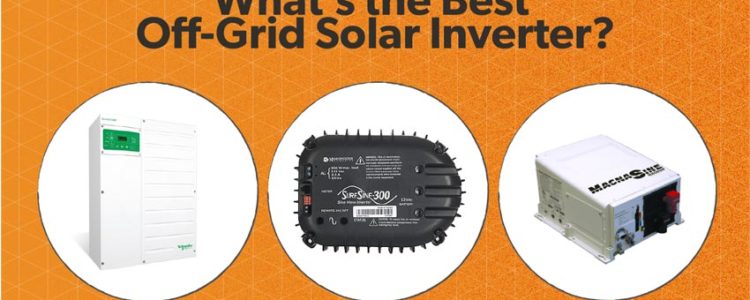
WHAT’S THE BEST OFF-GRID SOLAR INVERTER? (2019 EDITION)

WHAT’S THE BEST OFF-GRID SOLAR INVERTER? (2019 EDITION)

By Josh Roelofs | April 23, 2018

Sharing is caring!182SHARES

What are the best off-grid solar inverters you can buy in 2019?

If you’ve spent any time researching solar energy, by now you’ve heard of an inverter.

The inverter is like your solar system’s brain. It manages your power flow, controlling two kinds of power.

DC—or direct current—power is the kind stored in batteries. It’s also the kind produced by solar panels.

But you can’t use DC power (directly) to power anything in your home. That’s where your inverter comes in.

Everything in your home uses AC—or alternating current—power. And an inverter takes DC power from your panels (or from batteries) and turns it into AC so it can be used for your fridge, lights, TV, and other household appliances.

Simple, right?

How is an off-grid inverter different from a grid-tied inverter?

A grid-tied inverter takes DC power from solar panels, turns it into AC, and sends it into the grid for credit.

Grid-tied inverters are simpler and easier to wire since there are usually only two main components—the inverter itself and your solar panels. (Some grid-tied systems are starting to incorporate energy storage, but most don’t have any batteries at all.)

But an off-grid inverter needs a battery bank to function.

How a grid-tied solar inverter works

How an off-grid solar inverter works

Here’s how it works: your solar panels feed DC power into the batteries. Then your inverter takes that power and “inverts” it, creating AC power for your home. This works essentially like a miniature power grid.

(In case you’re curious, no, your inverter won’t deplete your batteries provided your system is set up and designed right. The battery bank gets recharged by your solar panels and a charge controller, and by a backup generator in the winter months.)

As you might imagine, off-grid systems are more complicated, thanks to additional components like the charge controller, battery monitor, and additional AC and DC circuit breakers. All of these things tend to make off-grid systems more difficult to wire and install.

It can also be a challenge to buy off-grid equipment because there are a lot of associated accessories: remote controls, battery monitor, breakers and enclosures, surge suppressors, and so on.

Picking the right parts can be confusing enough—but there’s no more critical decision than buying the right inverter.

How to Pick the Best Off-Grid Inverter

Think About Size

The first thing to think about is how much power you need.

Fortunately, sizing off-grid inverters is straightforward if you know what appliances you’re going to use.

Add up the wattage of all your lights and appliances to calculate the number of watts you’d need if everything was used all at once. (No, you’re not likely going to use everything, but this is an easy way to be safe.)

solar inverter guide

Free Solar Inverter Guide

Learn More »

Don’t forget to consider the voltage—although most appliances run on 120Vac, some appliances, such as well pumps, require 240Vac.ExampleLet’s say you need 1,000 watts for your fridge, 500 watts for lights, and 200 watts for your phone & TV. That adds up to 1,700 watts. In this case, we’d suggest a minimum inverter size of at least 2,000 watts to give you a little extra headroom. (After all, you may add appliances in the future.)

What’s the most popular size we sell? 4kW followed by 8kW. Different models and brands are available in various sizes and most of them can be stacked together for higher power output.

Consider Pure Sine Wave Instead of Modified Sine Wave

You may hear some manufactures talk about pure sine wave inverters. You don’t need to understand exactly how these work—it’s enough to know that the power that’s put out by a pure sine wave inverter is “cleaner” than what you’d get from a modified sine wave inverter.

Pure sine wave inverters deliver higher quality power output, similar to (or better than) our power grid. Modified sine wave inverters are cheaper, but they deliver lower-quality power output.

For this reason, modified sine wave inverters can cause issues with certain appliances. Motors, pumps and compressors run hotter and wear out more quickly. Certain sensitive appliances like computers can be damaged, or they may not work at all. These inverters also typically cause background noise on a stereo, and reduced video and audio quality for certain TVs.

That’s why we don’t recommend modified sine wave inverters for most applications; most of our off-grid customers are use pure sine wave inverters to avoid these potential issues.

Need a quick way to tell the difference? Look at your inverter’s total harmonic distortion (THD) rating. THD is an indicator of power quality output and will be listed on the spec sheet of any decent inverter.Rule of ThumbTo avoid running into trouble, choose a pure sign wave inverter with THD of 5% or less.

Look at the Technical Specs

Here are some other technical specs to consider:

  • Efficiency. This is a measure of how much power from the batteries your inverter delivers to your home when it’s operating in perfect conditions. A good peak efficiency rating is around 94% to 96%.
  • Self-consumption, or no-load current draw. How much power will your inverter consume just sitting there? Obviously you want this to be as low as possible.
  • Surge capacity. How much short-term overload can the inverter handle before it “trips?” Some appliances, like pumps or fridges, need as much as 2x–3x their running power to start up.
  • Battery charger output. Many off-grid inverters include a battery charger, which is used to recharge your batteries during the winter months with a backup generator. The battery charger will have a rating, usually measured in amps. Most decent off-grid inverters will have a battery charger in the range of 50-100 amps DC.
  • Temperature range. Inverters are sensitive to extreme heat. Pay careful attention to the temperature range if you plan on installing your system in your garage or anywhere it could be exposed to temperature extremes.
  • Warranty. Warranties start at 1 year and typically range from 3-5 years, with a few manufacturers offering a 10 year warranty extension option.

You can normally find information on all these features on the product spec sheets. Check with your solar tech for help comparing and picking the right inverter.

Research Features

Your inverter may need special features. Look into these ones:

  • Battery charger. A charger allows your system to be charged from a backup AC generator. Most bigger inverters include this; these are called “inverter/chargers.”
  • Grid-tied capability. Some off-grid inverters have the added capability of feeding power into the grid, here are a few examples:
    • Outback FXR/VFXR
    • Outback Radian
    • Schneider XW+
    • SMA Sunny Island

    This capability is useful if the grid becomes available in the future, or if you are setting up a grid-tied system with battery backup.

  • Automatic generator start. Usually you’ll need an add-on accessory for this, although some inverters or charge controllers can take care of it.

Read Up on the Manufacturer

Knowing about the inverter manufacturer is also important. Check into their history and reputation. Off-grid inverters need to be on all day, 365 days a year, for several years at a time—so you’ll want to choose one from a manufacturer with a reputation for reliability.

In our experience, there are only a handful of companies making high quality inverters for this purpose:

Make Sure it Has UL Listings and Certifications

Off-grid inverters have a few different certifications required in the US, for safety and also to ensure code compliance.

Inverters for your home need to be UL 1741 listed. Mobile inverters for boats and RVs should carry a UL 458 certification. There are a few other requirements for different applications such as UL 1778 for uninterruptible power supplies and KKK-A-1822E standard for emergency services, such as ambulances.

There are other standards required outside of the US such as CSA 107.1 in Canada and IEEE 1547 used internationally outside of North America.

Don’t Forget Price!

You also need to look at the price of the inverter system (including all required components)—as well as the features you get for that price.

Make sure to compare the price of all required components, including the remote control, circuit breakers, mounting plate, and anything else required to install the system.

Another Good Option: Using a Pre-Wired Power Center

A power center is a pre-wired off-grid inverter system that includes everything you need: an inverter, charge controller, remote control, and circuit breakers.

Most of the power centers we sell also include some additional components for monitoring and protection, including a battery monitor, and surge suppressors.

We assemble power centers with all of these components, and then wire them up and test on our workbench to make sure the system is wired correctly and working.

Buyers, especially those looking to DIY, love power centers because you can add them to a solar installation by making only a few final connections. (We even label the connection points to help make it even easier.)

The Best Off-Grid Inverters in 2019

Your choice of inverter really depends on your size requirements and the application, but here are some of our favorites:

Our Pick For: Best Small Off-Grid Inverter

Best inverter for self-contained micro-systems: Morningstar SureSine

Morningstar SureSine

  • 300 watts 120Vac output
  • 12Vdc battery bank

This inverter is small. At just 300 watts of output power, it can handle lights, charging phones and tablets, and an efficient TV—and that’s about it.

But the SureSine is renowned for being extremely durable. It’s also used for industrial applications, powering remote equipment in harsh conditions all over the world.

It’s efficient, with very low self-consumption, which makes it ideal for smaller systems like a hunting cabin.

It’s also perfect for industrial remote power systems that require a small amount of 120Vac power.

Our Pick For: Best Off-Grid Inverter for Cabins & Small Homes

Best off-grid inverter for small cabins: Magnum MS-PAE

Magnum Energy MS-PAE

  • Two models: MS4024PAE and MS4448PAE
  • 4kW-4.4kW 120/240Vac output
  • 24-volt or 48-volt battery bank

The MS-PAE inverter series comes in two sizes: 4kW 24-volt, or 4.4kW 48-volt.

Magnum Energy inverters are fairly easy to set up and use. They have good surge capability and powerful battery chargers. They also have a nice Magnum Panel system that includes a back plate and breaker panel (to make a complete power center).

Installing these inverters on a Magnum Panel bumps up the standard warranty from three years to five.

There are accessories available, including a battery monitor, automatic generator start (AGS) and MagWeb kit for remote monitoring.
MS-PAE Magnum Power centers have been our best selling power centers for years, both for off-grid cabins and for small homes.

Multiple MS-PAE inverters can be stacked together—up to 4 inverters, or 17.6kW total—which makes this inverter also suitable for bigger off-grid homes.

The 4kW 24-volt model can work with smaller battery banks and solar arrays; that’s ideal for cabins.

Magnum inverters are available in a wide range of sizes, and they are relatively affordable and easy to set up, which makes them a great choice for off-grid cabins and homes.

Our Pick For: Best Large Off-Grid Inverter

Best off-grid inverter for large-scale applications: Schneider Conext XW+

Schneider Conext XW+

  • Two models: XW+ 5548 and XW+ 6848
  • 5.5-6.8kW 120/240V output
  • 48-volt battery bank

The XW+ inverter comes in two sizes: 5.5kW or 6.8kW output power. Both work with a 48-volt battery bank.

Multiple inverters can be stacked together, and groups of three can be combined for three-phase power systems.

Schneider offers several accessories including a power distribution panel, automatic generator start, and battery monitor. The Schneider XW+ system really excels with bigger, multi-inverter systems.

Schneider supports multiple clusters of inverters for large industrial and commercial applications, up to 102kW output power. They also support Lithium batteries.

All of these features, plus the ability to stack clusters of inverters, make the XW+ our choice for large off-grid power requirements.

BONUS PICK! Best Inverter for Grid-Tied Systems with Battery Backup

Best off-grid inverter that can convert to grid-tie battery backup systems: Outback Radian

Outback Power Radian

The Outback Radian is an off-grid inverter that can also tie into the grid to sell your excess power.

This is the ideal option if you want the combination of battery backup and grid-tied solar, or if you’re off-grid but you think access to the grid will become available in the future.

The Radian inverter system includes advanced software, called Optics RE, for remote monitoring and control, allowing you to monitor your system, get alerts about any faults, and change settings remotely. It can also control generators for basic automatic start and stop.

Currently this is the only battery-based inverter approved for grid-tied interconnection throughout the US. It’s also the only grid-tied battery backup inverter available that complies with the newest standards in CA and HI for connecting grid-tied systems.

It’s available in two sizes, 4kW or 8kW, and multiple inverters can be stacked together for up to 80kW of power.

This is our best selling inverter for grid-tied with battery backup; most customers opt for either one or two of the 8kW inverters (either 8kW or 16kW.)

Download your free solar inverter guide

Sharing is caring!

Whether it’s a smartwatch, fitness tracker or even a refrigerator,connected devices are already transforming our world. 

Multi-view streaming in a network camera means that separate video streams of zoomed-in sections can be viewed at the same time as the full overview image

 Multi-view streaming in retail

We are entering an era where billions of devices will be able to collect and transmit data via the internet, so much so that Gartner recently forecasted that there will be 6.4 billion connected ‘things’ used worldwide in 2016.

The hype around the IOT (Internet of Things) and smart technologies is building at a phenomenal pace, it has become the buzzword of all buzzwords within the t media and the bandwagon is set to keep on rolling, with everyone from car makers to home appliance companies hoping to ride on its success.

Despite its hype, smart, connected products do represent a very real and practical step forward in how to connect disparate machines and widely dispersed data. As companies begin to understand the value of IoT, the focus will increasingly shift towards evaluating IoT technology via the underlying principles that guide most businesses today, focusing on improving productivity and efficiency and generating a return on investment. Commercial IoT solutions in the enterprise space will gain traction and businesses will be start to monetise the mass of data that IoT devices can provide.

As the evolution of the physical security industry has shown us, consumer and IT technology has had a profound effect on driving innovation and change with the security industry, HDTV, H264 compression and Power over Ethernet being notable examples. With this in mind the Internet of Things is also set to have profound ramifications on the security and video surveillance industry.

In 1996 Axis Communications introduced what many consider a pioneering IoT device (long before the term existed) when we launched the security industry’s first network camera. Little did we know it would ultimately spawn a tidal wave far beyond security.

What we can be certain of is that the concept of network cameras has come a long way in 20 years. Yet if we were to rank the top emerging trends for 2016, connected systems would still have to be at the top.

Why? Because the capabilities of IP-based systems are constantly evolving and suppliers of all types are still discovering new ways to leverage the power, flexibility and reach of connectivity.

As more IP-based security devices inevitably replace aging analog systems, we will see wider use of security products that integrate the growing wealth of information generated by the IoT into not just information for security purposes, but a range of other applications and uses.

IoT will allow network cameras to think independently and make smart decisions on their own. Imagine a mesh of network cameras that correspond between each other to alert the next camera of a person or object entering shortly from the left of a given scene. IoT-enabled cameras may also be able to cover up for one of their peers being damaged or obstructed.

From cool features to useful solutions

As enthralled as we are with the individual capabilities of IoT devices, in the security world the more important aspect of this trend is how all the components work together to solve a tangible challenge. First of all, IoT-based systems must be easy to design, install, maintain and use. And one size does not fit all.

To maximise the potential of IoT, it requires an in-depth knowledge by suppliers who 1) understand how each feature or component works together, 2) can design a solution that can be used to solve specific challenges, and 3) are able deliver it as an integrated offering whose long-term value has more value than just the sum of its parts.

This is especially true as security solutions move well beyond their roots in cameras. Indeed, largely because of IoT, the security sector’s traditional boundaries continue to blur. For example, network cameras can be used for Building Information Management (BIM), Business Intelligence (BI) in retail and even leaping into scientific research with real-time analysis of traffic patterns and crowd movements. IoT will allow for combined systems integrating previously disparate devices such as video surveillance cameras, smoke detectors,  access control panels and loudspeakers into a common management console providing a ‘single pane of glass’ overview across entire buildings and sites.

The result is a huge opportunity for security solutions that are purpose-built to share useful data with other connected devices, all of which can be monitored remotely. This connectivity between devices will provide end users with more complete situational awareness across multiple locations.

Axis Communications itself is branching out and has introduced IP-based loudspeakers and door controllers, for example, enabling not just an Internet of Things, but a step towards truly smart buildings.

With the increasing amount of data being generated, shared over the network, and, in many cases, stored and accessed through cloud computing models (see below), there is a growing need to focus on the protection of all this data and assets that exist ‘virtually.’

New technologies and methods for enhancing cyber security specifically for networked and cloud-based security systems are emerging. This is critical to protect against vulnerabilities, such as hacking, and will be an important aspect of how physical security and surveillance solutions are designed and implemented.

Security as a service: The cloud emerges

Cloud-based computing has touched just about every industry and it will continue to reshape the security and surveillance sector as well. Security can now be offered as a service that is managed remotely, freeing up valuable human and capital resources that no longer need to be on site at every location that requires monitoring. Secure remote access to security systems will increase in use, including by end users who want the convenience and real-time benefits of being able to monitor property and events without having to be physically present.

Cloud storage is another important aspect of how systems are becoming more efficient in this model. Much larger volumes of data can be stored, cost-effectively and securely, at dedicated server facilities, allowing users to archive video and associated data for longer periods of time and improve its accessibility as well.

More cameras mean Big Data

According to market researchers, video is now the fastest growing type of data in the world, and video generated by security and surveillance systems is no small reason. While this vast amount of video data is largely being used for security purposes, as mentioned above, it is increasingly valuable as a source of business intelligence.

However, there still remains a significant challenge to effectively manage and use the endless amounts of video data being generated, so-called big data.

Big data is difficult to process through traditional data processing applications. We expect to see more investment in tools and other resources that can effectively mine and derive actionable intelligence from the big data that security systems are producing.

This technology can put structure around vast amounts of unstructured video data, helping better understand significant patterns and trends.

In the coming years, look for improvements in and greater use of video management systems (VMS) to search big data in order to pull up relevant events, people, locations, times, colors and keywords. Such tools will assist business operators to turn big data into critical information that aids in loss prevention, marketing, operations, and customer service.

Cutting the cords

Wireless technology has transformed our lives in many ways, from mobile phones, to WiFi connectivity. We have already seen the benefit and convenience of remote security monitoring via smartphones and tablets. Video surveillance systems of up to ten network cameras can be managed entirely via mobile devices, no longer requiring a desktop PC to run video management software. Especially for SMBs, this significantly lowers the technology hurdle as users are more open to using a smartphone app than having to overlook a more comprehensive and detailed video management software on a desktop PC. It also reduces overall system and maintenance costs.

Expect to see more use of wireless technology in security and video surveillance, particularly as an enhancement to business optimisation and improvement of the customer experience.

The never-ending quest for more detail

Security operators have an insatiable appetite for more clarity and detail in the images produced by their video surveillance systems. This is especially true as the adoption of intelligent video analytics continues to grow.

So continued improvement in megapixel technology is certainly in our future. Enhanced techniques to handle challenging low-lighting conditions in new ways are coming to market, making cameras even more useful in a wider array of applications and use cases. These improvements, largely focused on expanding the wide dynamic range (WDR) capability of cameras, also provide enhanced detail for analytics to help decipher information. Look for continued adoption of 4K Ultra HD, which enables network cameras to see more details. With an HDTV or megapixel network camera, the resolution is at least three times better than an analog CCTV camera. And 4K Ultra HD offers four times the resolution of HDTV 1080p.


However, higher and higher resolutions also result in increasing storage consumption. Intelligent video compression algorithms such as Axis’ Zipstream technology allow for a reduction in storage needs by an average 50% or more.

This is achieved by analysing and optimising a network camera’s video stream in real-time. Scenes containing interesting details are recorded in full image quality and resolution while other areas are filtered out to optimally use available storage. Important forensic details like faces, tattoos or license plates are isolated and preserved, while irrelevant areas such as white walls, lawns and vegetation are sacrificed by smoothing in order to achieve better storage savings.

Analytics provides the brain for smarter systems

If IoT devices are the eyes and ears for increasingly interconnected systems, then analytics technology is the brain. We expect to see continued adoption of sophisticated video and audio analytics in the coming year, helping security systems evolve from passive monitoring to intelligent and adaptive recognition, situational awareness and analysis systems.

Analytics go far beyond security uses. Retailers, for example, are increasingly using video analytics to gain business intelligence insights that allow them to optimise shop floor plans, merchandise display or checkout queue management.

In our recent survey, ‘CCTV in Retail’, one third of retailers across Northern Europe want better customer insights such as age and gender analytics and other IP applications such as people counting, queue management and dwell time. This opens up entirely new user groups to video surveillance. For example, in-store traffic flow and behavior analysis can help guide advertising and promotion campaigns.

A growing concern for cyber security threats

While the vision of IoT is enticing for the convenience, capabilities and flexibility vast networks of connected devices offer, there is a growing risk for security threats and breaches as the number of entry points into a network dramatically increases. In a recent survey by Cisco, 73 percent of business decision makers said they expect the IoT to cause security threats to increase in severity over the next two years. More worrying, 78 percent of IT security professionals are either unsure about their capabilities, or believe they lack the visibility and management required to secure new kinds of network connected devices.

As a general rule of thumb, as you increase availability and access to any network device, it potentially increases exposure to cyber threats. Because security camera systems will become increasingly internet connected with the rise of the Internet of Security things, offering benefits such as remote access and third party integration, just as with other network connected devices, it is critical to do a risk assessment and implement security polices in the design and implementation of a network video system.

Risk assessments have been common practice in the design of physical security systems for years, particularly for enterprise installations. Integrators should apply the same thought process to the configuration of network video devices, even though unlike other devices on the networks such as laptops, desktop or mobile devices, a network camera is not exposed to the common threat of users visiting potentially harmful websites, opening malicious email attachments or installing untrusted applications.

However, as a network device, a camera or other connected physical security devices may expose risk. Consequently it is important to reduce the exposure area of these risks and minimising the attack surface area is a common cyber protection measure.  If devices, services and applications do not need to interact you should try to limit connectivity between them.  Additionally segmenting the video system from the core network is a good overall protection measure, thereby reducing risks of video resources and business resources adversely effecting each other.

The process of securing a video security system – or hardening it – is an increasingly necessary one for installers and IT personnel to understand. A good hardening guide provides a configuration strategy suited to specific user requirements to deal with the evolving threat landscape.

Axis uses the SANS Top 20 Critical Security Controls as a baseline for its hardening guide. A first step is an understanding and use of industry standard security protocols, including multi-level user authentication/authorisation, password protection, SSL/TLS encryption, 802.1X, IP-filtering and certificate management.

In addition, smart camera suppliers like Axis continuously update their cameras firmware with new features, bug fixes and security patches. To deal with the increasing risk, variety and volume of security risks, security systems users will need to stay on top of updates from their suppliers and take heed of best practices for preventing attacks through network camera-based systems.

Construction site arrest

CCTV and security monitoring has changed significantly over the past 70 years. From analogue to digital capture, the popularity of the platform increased dramatically along with its ease of use.

 Innovation and changes in key pieces of software can be great for customers, but a headache for installers. Advances in technology have meant there is more choice for customers, whether they are securing a residential site or a large business. In this blog, we take a look at how far CCTV has come, and what this means for installers and end users in the future.

Timeline of innovation: the history of CCTV

A lot has changed in 70 years, especially when it comes to CCTV and security monitoring. We’ve put together a few key moments in the history of CCTV.

1942: The first use of CCTV

Set up in Germany over 70 years ago, the first use of CCTV monitored rocket testing.

1949: The first commercial use of CCTV

An American government contractor, Vericon, began promoting an early version of CCTV.

1966: The home security system is created

Marie Van Brittan Brown invented the first home security system, which incorporated a series of peepholes and cameras, as well as remote controlled door latch. The patent for her solution was granted three years later, in 1969.

1970s: VCR introduced into CCTV

Prior to the ‘70s, CCTV wasn’t particularly popular, due to a lengthy, manual process, and several expensive components. With the introduction of VCR, it became much easier to record and erase information, making it easier to adopt.

1990s: Multiplexing

This tool allowed several cameras to record at the same time, and viewed from just one monitor. The introduction of multiplexing meant CCTV was now more efficient.

1996: Farsight is established

20 years ago, Farsight launched! The founders of Farsight Security Services launched the business after noticing potential for ‘event driven CCTV’, with Farsight leading the way in the industry.

2000s: The rise of digital

CCTV became much easier to adopt, and more user-friendly, as VCRs were replaced with digital recorders. The introduction of digital recording also meant businesses no longer needed to stockpile old CCTV recordings.

2002: CCTV Security standard BS8418 launches

With the CCTV gaining popularity, it was the right time to introduce regulations for the industry. In 2005 Farsight became the UK’s first BS8418 compliant Remote Video Receiving Centre (RVRC).

2014: IP cameras overtake analogue.

IP cameras utilise the internet to transmit footage in digital form, making it available on a number of sources. With the popularity of digital tools increasing, this was the first year when digital cameras and devices over took older tools – signalling a shift in CCTV technology.

2015: Farsight launches SureSight

Farsight introduced SureSight in 2015 to provide installers with an easy to manage solution when commissioning new sites, whilst also allowing customers to utilising cloud monitoring.

2016: Farsight launches YourSight

Farsight launched YourSight to replace the previous Farsight Web Portal and Fault Tracker. YourSight was developed specifically with our customers in mind, and is a complete overhaul of the previous system. YourSight is a user-friendly solution with allowing for unbeatable communication between Farsight operators, installers and end-users.

What does innovation mean for installers?

In 2014 digital overtook analogue recording, which signalled a shift in CCTV and remote monitoring for end users and installers. As more customers are embracing new technology, it’s key that installers and end users stay up to date with changes to the industry.

New CCTV technology has offered end users increased efficiency and better security, and the future of remote monitoring should only continue to offer a more refined service, whilst also keeping customers secure.

The Future of Renewable Energy

Green’s all the rage these days, but as the market gets flooded with everything from hybrid cars to reusable shopping bags (even Subway is hawking them now), the ability to do something truly innovative will be paramount. Here are five companies that are leading the charge to recycle the green movement’s relevancy.

 IST Energy

The company: IST Energy

The innovation:
 The Green Energy Machine

What it does:
 The short answer: It eats trash and craps money. The longer, relatively more scientific version: It can take up to three tons of trash a day and mash it down into pellets that are converted into gas electricity. It’s ideal for large facilities like schools and hospitals, where, in addition to providing cheaper electricity, it can reduce waste disposal costs by 95 percent.

How it makes money:
 The $850,000 price tag doesn’t hurt, nor does having large, well-backed customers. But it also saves those customers a ton of money, and pays for itself within three to four years.

Where it’s going: GEM can be compartmentalized into two halves–the masher and the gasser–so it can be used by cities to collect trash in one place and create electricity in another. A smaller version might also be in the works, and, further down the road, IST CEO Stu Haber says the company might think about collecting the trash itself and using GEM to create and sell power.

Energy Solutions International and Green Revolution

The companies: Energy Solutions International and Green Revolution

The innovation: Kinetic energy adapters for gym equipment

What it does: Technically, nothing. It just sits there while you pedal furiously and go nowhere. But it does allow you to convert all that sweat and energy into, well, energy, as resistance from stationary bikes is converted into electricity and sent back to the gym’s power grid.

How it makes money: “By being able to build a better mousetrap,” says Chris Maddern of Energy Solutions International. “What you have to do is really be able to stay at the forefront of technology so that less energy is being wasted when it’s transferred from the generating source to the consuming source. As you move on, your product has to become more and more efficient.”

Where it’s going: Maddern says his firm and Green Revolution are working on an initiative to create completely self-sustaining gyms where members could go online to keep track of how much energy they’ve produced and the resulting carbon offset.

 Great Plains

The company: Great Plains

The innovation: Biodiesel made from camelina

What it does: For starters, camelina can grow just about anywhere and, unlike soy, it’s really not good for much else anyway. Great Plains founder Sam Huttenbauer originally wanted to use the plant to create therapeutic proteins and discovered that almost half of the crop seed was oily waste. Now the company is on its third crop cycle and is aiming to plant a million acres of the stuff in the next five years, which would produce about 100 million gallons of fuel.

How it makes money: “We came at it from the opposite end that most players have come at it from,” Huttenbauer says. “They came at it from the production side and were looking to source their materials and then sell it as a fuel. We came at it from the seed development and the growing of the crop. Our ultimate outlet is going to be direct to consumers or direct to businesses.”

Where it’s going: Quite literally, up, as Great Plains moves forward with a plan to develop a completely substitutable jet fuel. But overall, the potential seems limitless. “We’re really at the low-hanging-fruit stage, and with our wide variety of germplasm we’re able to breed and create even better-yielding crops, which will ultimately bring the cost down. That’s really the exciting thing here. We’re really starting from ground zero.”

Little Foot Energy

The innovation: Energy production through waste heatWhat it does: It takes all that hot water you waste during your 45-minute shower and uses the heat from it to power your air conditioning. It’s also used in industrial settings to recycle the heat used in various processes and redistribute it to other parts of the plant.

How it makes money: Eight-figure revenues for 2008 would certainly suggest that it does, and through good old-fashioned economics. “We can produce heat at under a dollar per thermal unit,” CEO Kevin Poulsen says. “When you compare that to natural gas, you’re talking about something that could run $1.50 to $2 per thermal unit to produce that same amount of energy. That arbitrage that we’re able to play there is our opportunity.”

Where it’s going: A design is in the works for a coin-operated laundry facility that would use exhaust heat from the dryers to heat water for the washers. And if you think the endgame is curing the world of its addiction to fossil fuels, think again. “We’re not trying to give you that one little pill that will change everything,” Elia Kleiman, director of application development, says. “It’s the existent, verified and hard-working technologies out there that will slowly change it to a different feel for business.”

Borrego Solar Systems

The innovation: Modern business practices applied to green energy

What it does: It makes solar energy affordable for the consumer while making it even more profitable for the producer. Using power purchase agreements, Borrego allows its customers to defray upfront equipment costs and pay only for the energy they use. The company was also an early adopter in terms of using technology in an effort to put more focus on marketing and customer service than its contractor competitors.

How it makes money: By setting itself apart from the competition. “We have to be very conscious of how we’re different from our competition because the last thing we want is to be a commodity where you might not care what brand you have–you just want the lowest cost,” CEO Aaron Hall says. “If we’re competing against all the other people out there providing solar solutions on cost, it would be very challenging, and that’s not a business model you want to have.” Whatever Hall’s doing, it works–the company made $70 million in 2008.

Where it’s going: Physically, to the East Coast, where the company began expanding in 2007, and to schools. Philosophically, toward–Hall hopes–what is known in the renewably energy community as “grid parity,” a world in which solar can compete with traditional utility companies without the benefit of government incentives. “If we can compete with them, there’s unlimited demand.”

The Future of Power

The human race, in its never ending struggle to improve its standard of living, has invariably depended on colossal amounts of electric power to fuel our evolution. A present day estimate by National Geographic determined that we use 320 billion kilowatt-hours of energy every day. Today, most of this enormous requirement is addressed by burning fossil fuels. So far, fossil fuels have catered to our energy needs very efficiently, but they are also non-renewable and rapidly depleting. These fuel sources have also contributed greatly to greenhouse gas emissions and pollution. The time has come to find suitable and better replacements for fossil fuels. Scientists are constantly researching newer and greener sources of energy that have limited impact on the environment and reduce their contribution to global warming, which is believed to be caused by the release of carbon dioxide while burning fossil fuels.

Atomic energy, solar energy, and energy from wind and bio fuels are just a few of the promising alternatives for a cleaner and greener future. Other relatively new sources of energy such as fuel cells, geothermal energy, and ocean energy are also being explored. In the following sections, we’ll take a look at current sources of energy as well as discuss possible future energy sources.

(1) Fossil Fuels – Coal:
Fossil fuels are the remains of dead plants and animals on land and in the seabed. These are formed from the fossilized remains of dead animals and plants that are exposed to heat and pressure in the earth’s crust for hundreds of millions of years.

Fossil fuels primarily consist of hydrocarbons. They contain carbon and hydrogen in varying ratios, such as methane, that has a low carbon to hydrogen ratio, or anthracite coal, which is almost pure carbon. Hydrocarbons are formed when the fossilized remains of dead organisms are chemically altered over hundreds of millions of years by intense pressure and heat found in the earth’s crust. The chemical energy ‘stored’ in these fuels is released during combustion to produce electric power.

According to estimates provided by the Energy Information Administration, fossil fuels account for 86% of the total energy produced in the world. Of this, petroleum accounted for 36.8%, coal 26.6% and natural gas 22.9%.

However, fossil fuels are non-renewable sources of energy. They take hundreds of millions of years to form and are depleted much faster than new reserves can be created. It is estimated that 23.5 tons of fossilized organic material deposited on the ocean floor is required to produce 1 liter of gasoline. In 1997, the total amount of fossil fuel used was equivalent to plant matter that grew on the entire land and ocean surface of the earth over a period of 422 years.

Another disadvantage of our heavy dependence on fossil fuels is the amount of carbon dioxide produced during combustion, which is estimated at 21.3 billion tons per year. However, natural processes are capable of absorbing only about half of the total amount of carbon dioxide emissions released into the atmosphere, which means every year the amount of carbon dioxide in the atmosphere is increasing by 10.65 billion tons, which is theorized to be the leading contributor to global warming that could potentially have very adverse effects on the ecosystem.

(2) Fossil Fuels – Natural Gas:
Natural gas is usually found along with fossil fuels, in coal-beds and trapped in other types of rock. It is created by methanogenic organisms present in landfills, marshes and wetlands. It naturally consists of methane and small amounts of other gases such as ethane, propane, butane, pentane, hydrocarbons of higher molecular weight, sulfur, helium and nitrogen. The constituents of natural gas other than methane need to be removed before natural gas can be used as a source of fuel.  Read Natural Gas Generators: An Alternative to Diesel, for one example showing existing technology using a natural resource, one that is better for the environment, as fuel.

Although natural gas is considered to be cleaner than other fossil fuels, it has still been found to contribute to pollution and global warming. While it can be used to supplement the world’s ever depleting reserves of traditional fossil fuels, it is not a 100% clean, non-polluting alternative. In 2004, carbon dioxide emissions resulting from the use of natural gas stood at 5,300 million tons while coal and oil contributed to carbon dioxide emissions of 10,600 million tons and 10,200 million tons, respectively. However, this trend is expected to reverse by 2030 when natural gas is likely to emit 11,000 million tons of carbon dioxide as opposed to 8,400 million tons from coal and 17,200 tons from oil at that time. Also, when released directly into the atmosphere, natural gas is a far more potent greenhouse gas than carbon dioxide but since this occurs in very small amounts, it is currently not a major cause of concern.

(3) Solar Energy:
Almost everything in this world ultimately derives its energy from the sun. Instead of obtaining the sun’s energy from indirect sources like fossil fuels, researchers and organizations worldwide are looking to directly tap this unlimited source of energy.

The earth receives about 174 billion megawatts of power at the upper atmosphere as a result of solar radiation. About 30% of the incident solar radiation is reflected back, while the remaining, which amounts to 3.85 x 1024 Joules every year, is absorbed by the atmosphere, oceans and landmasses. The amount of solar energy that is available to us during an hour is more than the total amount of energy consumed worldwide in an entire year. But this is a diffused, rather than concentrated, form of energy and the greatest challenge lies in harnessing it.

Heat and light radiation from the sun can be harnessed through the use of semiconductor solar panels. The energy solar radiation excites electrons on these panels and leads to the production of electrical energy.

One of the biggest hurdles in harnessing the energy from the sun is in building cost-effective solar panels. The cost of solar power is about US 8–15 cents per kilowatt-hour as compared to the cost of coal-based electric power at US 6 cents per kilowatt-hour.

Proper storage of energy is another major obstacle. Solar energy is not available at night but modern energy systems usually assume continuous availability of energy. Thermal mass systems, thermal storage systems, phase change materials, off-grid photovoltaic systems, and pumped storage hydroelectricity systems are some of the ways in which solar energy can be stored for later use.

Even with all of the technological advancements, solar energy technology is still in its infancy. Until we perfect the technology and are able to harness and store solar energy in a viable and cost-effective manner, fossil fuels will continue to be the most commonly used source of energy.

Nuclear Energy:
As the worldwide demand for power continues to surge, nuclear energy is gaining increasing importance as a clean source of power that is expected to address the global issue of climate change. Volatility in the prices of fossil fuels and the increasing concern of nations to secure energy supplies are other drivers of nuclear energy.

There are currently 439 nuclear power reactors operational in 30 countries worldwide. This accounts for 14% of the total power generation of the world. The International Atomic Energy Agency (IAEA) expects the global nuclear power generation capacity to increase from the current 372 gigawatts (GW) to 437–542 GW by 2020 and to 473–748 GW by 2030. However, for nuclear power to emerge as a reliable and clean source of energy, several challenges need to be addressed. Some of these include improvement in economic competitiveness, designing safe and reliable nuclear power plants, management of spent fuel and disposal of radioactive waste, developing adequate skilled workforce, ensuring public confidence in nuclear power, and ensuring nuclear non-proliferation and security.

Nuclear energy is harnessed by either splitting (fission) or merging (fusion) the nuclei of two or more atoms. Nuclear fission usually uses uranium in the process of harnessing energy. At our current rates of consumption, the uranium found in the Earth’s crust can last us about a century. However researchers predict that the energy consumption will triple in the next century, which means that the available uranium resources will only last us for approximately 30 years. One option is the reprocessing of the spent fuel. This spent fuel is rich in plutonium and when combined with the leftover uranium, it can be reprocessed into a mixture known as MOX, which can be used as fuel. This may help to stretch the available uranium resources by a few more decades. The biggest drawback to this source of energy is the disposal of radioactive waste and the high cost of building nuclear power plants.

Nuclear fission, on the other hand, could be the answer to our energy problems. Fission utilizes hydrogen isotopes, lithium, and boron. The lithium reserves from the earth, combined with those from the sea, can last us for more than 60 million years. Deuterium, an isotope of hydrogen, can last another 250 million years. However, the process of harnessing energy from this isotope is fairly complicated and is still in its infancy. If we can successfully learn how to utilize nuclear fusion for the generation of energy in a viable manner, it could well be the new king of the energy world. Nuclear fusion is a clean process, with low carbon dioxide emissions, and the radioactive waste products also have a relatively short half-life.

Wind Energy:
Wind farms are constructed to harness mechanical energy from the wind and convert it into electrical energy. These wind farms are then connected to electrical power transmission networks for the distribution of power. On average, only 20 to 40 percent of the total energy capacity of a wind farm can be utilized.

The limiting factor in harnessing energy from wind is that wind speed is variable and in most cases the energy from wind can only be effectively harnessed with very high wind speed and consistent heavy winds. These generally occur at higher altitudes. Wind energy also requires large, open expanses of land in order to construct wind farms.

In 2008, the worldwide wind power generation capacity stood at 121.2 GW. On an average, wind power currently accounts for only 1.5% of the global power generation capacity. However, this sector has grown two-fold within the three-year period of 2005–2008. Wind power accounts for 19% of the total power generation in Denmark, 10% in Portugal and Spain, and 7% in the Republic of Ireland and Germany.

Biofuels and Biomass:
These include fuel from plant and animal sources. Oil, or ethanol, obtained from plants such as sugarcane, switchgrass, algae, poplar, and corn can be used directly or mixed with other fuels such as commercial diesel and gasoline to provide power. Even plant matter such as dead wood, leaves, wood chips, and branches can be burnt to produce energy. This is typically classified as biomass. Biomass also includes any biodegradable waste from plant and animal sources which can be burnt for fuel.

The limiting factor in using bio fuels is that a large number of crops need to be grown to harvest the energy trapped in plants. This requires vast areas of fertile land. Additionally, not all plant sources offer a high yield. Experiments are underway to hybridize and genetically alter these crops to make them more robust and increase their yield. Biofuels are very promising for small-scale use as they are low on greenhouse gas emission, are an effective waste management system, and produce little air pollutants.

With the advancement of new technology and the development of new insights into our surroundings, scientists have been able to come up with even more adventurous power options. These include fuel cells, geothermal energy, and tidal and wave energy, to name a few.

Fuel Cells:
Fuel cells are similar to batteries but use reactants from an external source, as opposed to batteries which are self contained. If the fuel and oxidant levels in fuel cells are properly maintained, power can be generated almost continuously. The efficiency of fuel cells is proportional to the power being drawn from it. They are also lightweight and extremely reliable.

Geothermal energy:
The interior of the Earth contains a lot of heat. Shallow regions contain hot water, rock and steam. Deeper inside, the magma is intensely hot. This heat can be harnessed to produce electrical energy and drive various applications. Harnessing geothermal energy requires no fuel and minimal land. It is relatively cheap and a very sustainable source of energy since the amount of heat contained in the earth bed is so vast that even if we harness more energy than we require, it will still suffice for millions of years to come.

Oceanic Energy:
The oceans are vast and contain huge amounts of energy in the water currents, and thermal and salinity gradients. The energy from tides and waves can be harnessed to produce electrical energy. The differences in temperature that occur with varying depths can be used to drive heat engines, which in turn produce electric power. The osmotic pressure difference between salt water and fresh water can also be used to generate electricity. Although most of these methods are still in the experimental stages, if researched properly, they can be a breakthrough for mankind. The oceans may well be able to quench our thirst for energy and bag the crown as the king of fuels.

Energy from Antimatter:
One of the most complicated theories of producing energy is the idea of using matter and anti-matter to generate electric power. Antimatter is the opposite of matter. If matter is comprised of particles, anti matter is comprised of anti-particles. Scientists propose that if matter and anti matter were to collide, they would annihilate one another and release vast amounts of energy. However, this is still a theoretical source of energy. Whether anti-matter exists in some part of the universe and can be harnessed in some way is still a mystery to humankind.

There are various ways of extracting energy from the earth that humankind has discovered and used to its advantage. As the human race evolves, we will continually search for newer, more efficient forms of energy that have the least amount of impact on the environment. At present day, the most economically efficient fuel has proved to be oil. In the future, when the world’s oil reserves are depleted, we will use another source of energy; possibly one that is mentioned above. However, the fact of the matter is that we must be proactive in researching new forms of energy to continue the advancement of civilization and to ensure a high quality of living that we all have grown accustomed to.

Calculation of currents & power

Currents and power analysis are key factors in any design or redesign of an installation they will enable the source(s) to be sized according to the purpose of the installation, the intended use of the circuits and the receivers to be supplied.

The current consumed Ia corresponds to the nominal current consumed by a receiver independently of the utilisation factor and the coincidence factor, but taking into account the aspects of efficiency (η factor), displacement factor or phase shift (cos φ) for motors or other inductive or capacitive loads.

For non-linear (or distorting) loads, the quadratic sum of the fundamental current and the harmonic currents must be calculated in order to obtain the actual rms current.

Let’s break the calculation of the power into few parts, so we can easily follow:

  1. Purely resistive load
  2. Non-distorting load that is not purely resistive
  3. Calculation of the current
  4. Overloads on conductors according to the total harmonic distortion
  5. Distorting load that is not purely resistive

1. Purely resistive load

The current consumed Ia of a purely resistive load is calculated by simply applying the formulas. For single phase:

Current consumed for single-phase

and for the three-phase:

Current consumed for three-phase
But beware, very few loads are totally resistive. Incandescent lighting is losing ground to solutions that offer higher performance levels, but which are on the other hand less “pure” from an electrical viewpoint.

Go back to currents and power calculations ↑

2. Non-distorting load that is not purely resistive

The nominal power (Pn) of a motor corresponds to the mechanical power available on its shaft. The actual power consumed (Pa)corresponds to the active power carried by the line.

This is dependent on the efficiency of the motor:

The actual power consumed (Pa)

The current consumed (Ia) is given by the following formulae. For single-phase:

Current consumed for single-phase

and for the three-phase:

Current consumed for three-phase

Where:

  • Ia – rms current consumed (in A)
  • Pn – nominal power (in W; this is the useful power)
  • U – voltage between phases in three-phase, and between phase and neutral in single-phase (in V)
  • η – efficiency
  • cosφ – displacement factor

Go back to currents and power calculations ↑

 3. Calculation of the current consumed by several receivers

The example described below shows that the current and power calculations must be carried out in accordance with precise mathematical rules in order to clearly distinguish the different components.

Example of asynchronous motors

A group of circuits consists of two three-phase asynchronous motors M1 and M2 connected to the same panel (mains supply: 400V AC – 50 hz). The nominal power of the motors are respectively: Pn1 = 22 kW and Pn2 = 37 kW.

The displacement factors are cosφ1 = 0.92 for M1 and cosφ2 = 0.72 for M2 the efficiencies are η1 = 0.91 and η0.93 respectively.

Calculation of the power consumed:

Calculation of the power consumed
The reactive power can in this case be calculated by determining the value of tanφ from cosφ. the relationship with the tangent is given by the formula:

Reactive power can in this case be calculated by determining the value of tan φ from cos φ
Calculation of the reactive power:

Calculation of the reactive power
Calculation of the apparent power:

Calculation of the apparent power
Calculation of the total current consumption for M1, M2, M1 M2 and the corresponding power factor:

Calculation of the total current consumption for M1, M2, M1 M2
The active power (in W) and the reactive power (in VAr) can be added together algebraically, while the apparent power and currents can only be added together geometrically.

Go back to currents and power calculations ↑

Presentation of the results

All power analyses must show, as in the table below, at least for each group of:

  • Active power circuits which corresponds (to the nearest efficiency) to the energy supplied,
  • Reactive power so that the compensation devices (capacitors) can be sized,
  • Apparent power so that the power of the source can be determined and
  • Current consumed so that the trunking and protection devices can be calculated.
M1 M2 M1 M2 (Total t)
Active power: P [kW] Pa1 = 24.18 Pa2 = 39.78 Pt = 63.96
Reactive power: Q [kVAR] Q1 = 10.30 Q2 = 38.35 Qt = 48.65
Apparent power: S [kVA] S1 = 26.28 S2 = 55.26 St = 80.36
Current consumed: Ia [A] Ia1 = 38 Ia2 = 80 Iat = 116
cosφ 0.92 0.72  0.80

Go back to currents and power calculations ↑

4. Overloads on conductors according to the total harmonic distortion

The current circulating in each phase is equal to the quadratic sum of the fundamental current (referred to as 1st harmonic order) and all the harmonic currents (of the following orders):

The current circulating in each phase
The THDi (Total Harmonic Distortion) expresses the ratio between the share of all the harmonic currents and the total current as a percentage.

THDi (Total Harmonic Distortion)

I1 being the rms value of the fundamental and in In the rms value of the nth order harmonic. The principle is to apply a current reduction factor that can be calculated based on the THDi.

For a permissible THDi value of 33%, the current must thus in theory be reduced in each phase by a factor K:

K factor for a permissible THDi value of 33%
If the factor is not applied, the current will then be increased by:

If the factor is not applied, the current will then be increased

This remains acceptable and explains why the standard does not recommend any derating or oversizing of cross-sections up to 33% THDi.

Above 33%. the standard recommends an increase in the current IB which results in necessary oversizing of the neutral conductor.

Reduction of the current or oversizing of multi-core cables may also be necessary for the phase conductors. It should be noted that the standard recommends a reduction factor of 0.84. which in fact corresponds to a pessimistic THDi of 65%.

K factor for pessimistic THDi of 65%
Related to the neutral conductor, it is considered that if all the harmonics are 3rd order and its multiples, they will be added together and the current due to the harmonics in the neutral will then be IN = 3 × Iph, which can be expressed using an equivalent notation, THDn = 3 THDi.

Devices whose load is said to be non-linear do not consume a current that is a reflection of the voltage applied. This leads to unnecessary power consumption: the distorting power that generates an additional current, the consequences of which must not be overlooked.

But this current is never expressed directly because it involves a fairly complex mathematical calculation, the fourier transform, to ascertain its relative overall part (THDi: total harmonic distortion) or the value order by order: ih2, ih3, ih4, ih5,..ihn.

With no precise measurements, it is difficult to know exactly the current level that corresponds to each harmonic order. It is therefore preferable to simply increase the cross-section of the neutral conductor as a precaution, since it is known that the main 3rdorder harmonics and their multiples are added together in the neutral. and to adapt the protection of this conductor.

Standard IEC 60364 indicates the increasing factors to be applied to the cross-section of the neutral conductor according the percentage of 3rd order harmonics.

In principle, the neutral must be the same cross-section as the phase conductor in all single-phase circuits. In three-phase circuits with a cross-section greater than 16 mm2 [25 mm2 aluminium]. The cross-section of the neutral can be reduced to cross-section/2.

 However this reduction is not permitted if:
  • The loads are not virtually balanced
  • The total 3rd order harmonic currents are greater than 15%

If this total is greater than 33%, the cross-section of the active conductors of multi-core cables is chosen by increasing the current In by a fixed multiplication factor of 1.65. For single-core cables, only the cross-section of the neutral is increased.

In practice, the increase of the current Ia in the neutral is compensated by an increase of its cross-section. When the neutral is loaded, a reduction factor of 0.86 is applied to the permissible current of cables with 3 or 1 conductors.

The current reduction factor KN or rather its inverse which will be used to oversize the neutral conductor will then be:

Current reduction factor Kn
With a total 3rd order harmonic distortion of 65%, the current of the phase conductors must be increased by 119% and that in the neutral conductor by 163%. If the THDi were to reach 100%, 1/KN would theoretically reach 2.12. This value would be impossible to reach as it would mean that the harmonic had totally replaced the fundamental.

The theoretical overcurrent limit for the neutral in relation to the phases is:

Theoretical overcurrent limit for the neutral in relation to the phases
These calculations demonstrate that the harmonic currents above all must not be ignored both in terms of “hidden” power consumption and in terms of sizing the conductors which may be overloaded. The relative complexity of the calculations leads to the use of generic derating values which normally cover most cases, just as software is used elsewhere.

Go back to currents and power calculations ↑

Example of following the standards for defining a protection device with neutral overloaded by harmonics

For a 3P N circuit, intended for 170 A, with TNS system, with total 3rd order harmonic distortion of more than 33%. When sizing the phase cables, the reduction factor of 0.84 (loaded neutral, see above) must be included.

This requires a minimum cross-section of 70 mm2 per phase. The neutral conductor must be sized to withstand a current of 1.45 × 170 A = 247 A, i.e. a cross-section of 95 mm2.

A circuit breaker must therefore be chosen that is capable of withstanding the current that may cross the neutral:

In device ≥ IB neutral ⇒ In = 250 A

But the device must be set according to the current that may flow in the phases:

Ir ≥ IB phases ⇒ Ir ≥ 170 A (and < 206 A, limit of the cable)

A 250 A unprotected interrupted neutral circuit breaker, set to 0.7 is therefore suitable for this application.

Go back to currents and power calculations ↑

5. Distorting load that is not purely resistive

The current consumed (Ia) is given by the following formulae:

Current consumed (Ia)

where:

  • Ia – rms current consumed (in A)
  • Pn – nominal power (in W; this is the useful power)
  • U – voltage between phases in three-phase, and between phase and neutral in single-phase (in V)
  • η – efficiency
  • PF – power factor

Go back to currents and power calculations ↑

Example of a fluorescent luminaire and electronic ballast

The nominal active power consumed by the luminaire is 9 W, and the measured apparent power is 16 VA. The measured displacement factor is cosφ = 0.845 and the power factor PF = 0.56.

The measured current consumed Ia is 0.07 A. As cosφ and the power factor are different, it is not possible to calculate the value of the tanφ or that of the reactive power Q (VAR) for the receiver in question.

The measured cosφ and power Q which would be calculated can only be calculated for the reactive power part connected with the sinusoidal component of the signal, in fact the current of the fundamental at 50Hz: 0.045 A measured in this case.

The powers relative to this linear and sinusoidal part of the load can be calculated as follows

  • S = 230 × 0.045 = 10.3 VA
  • P = S × cosφ = 10.3 × 0.85 = 8.7 W
  • Q = 5.5 VAR which is confirmed by the calculation of the power triangles Q2 = P2 – S2 or by the tanφ:
    Q = P × tanφ = 8.7 × 0.63 = 5.5 VAR
Therefore not all the apparent power consumed is linear as there is a significant difference between the measured total apparent power S (16 VA) and the calculated theoretical sinusoidal power (10.3 VA).

It can also be seen that the sinusoidal active power of the device 8.7 W is very similar to the measured total active power 9 W. It can therefore be deduced that a large part of power S (16 – 10.3 = 5.7 VA) is consumed without producing any active power. The fluorescent luminaire and electronic ballast in the example consumes unproductive power in the form of harmonic currents.

The total harmonic distortion is easy to calculate and represents expressed as a rate.

Total harmonic distortion
The spectral decomposition of the signal carried out on this luminaire shows that the main harmonic is 3rd order (34 mA) but that all the following odd-order harmonics are present and decaying. The main purpose of the above example is to demonstrate that active power information (in W) only for a non-linear receiver is very inadequate.

The cosφ has no real relevance or meaning as it is only applicable to the fundamental signal. Only the apparent power and power factor (PF or ?.,) information can really quantify and qualify the power that must be supplied by the source.

In the example given, it can be seen that an active power of approximately 9 W corresponds to a consumed power of 16 VA.

Many modern devices (light bulbs, computer equipment, domestic appliances and electronic equipment) have this particular feature of consuming non-linear currents. For domestic use, where only the power in W is billed (sic), the power savings shown for these products is attractive. In practice, the currents consumed are higher than it seems and the energy distributor is supplying wasted energy.

In large commercial or industrial installations the situation is different. A poor power factor results in consumption of reactive power that is billed. Compensation of non-linear loads thus becomes meaningful and useful here, but also at the design stage when it prevents oversizing of the energy sources, which it must be remembered supply VA (volt-amperes) and not W (watts).

Important: Unlike linear loads (page 29), for non-linear loads the active powers (in W) can be added together algebraically, the apparent powers must only be added together geometrically, and likewise the currents which must be the same order.

The reactive powers Q must not be added together except to as certain the relative part of the power associated with the sinusoidal fundamental signal and the part connected with the harmonic signals.

PoC/CoC Camera

About One Cable Solution – Camera Power supply & Control through coax cable

 One Cable Solution provides camera power through coaxial cable, so installation of camera power supply is not necessary.

Also, DVR can transmit camera control data through same coaxial cable, so camera’s all OSD menu control is possible. For AF camera models, Zoom/Focus, One-push auto focus control can be additionally supported.

One Cable Solution provides easy installation at actual installation sites. And besides, because DVR or CMS can control camera, it support efficient management of video surveillance system at the same time.

Full support of PoC/CoC (One Cable Solution) 

WEBGATE’S HD DVR, HD Camera have built-in PoC/CoC function for one cable solution, and they do not need additional equipment.

PoC/CoC products provide easier installation and operation environment than conventional analog system but because they can support high-performance Full-HD video surveillance system, they are attracting much attention of market.

PoC (Power over Coax)

The Ultimate performance PoC DVR series supply power to cameras through coaxial cables, so cameras don’t need additional installation for power supply. Besides, DVR provides auto-detection of PoC/Non-PoC camera, supports over-current alarm and its protection, status of PoC operation.By using WEBGATE’s recommended 5C-HFBT coaxial cable, PoC cameras can transmit HD-SDI video up to 200m. Moreover, PoC repeater RP101P can be used to extend the transmission distance. RP101P is a repeater which supports PoC function and because its power is supplied from DVR, it can be located anywhere without any restriction of installation.

•  Power through coaxial cable from DVR to camera
•  No additional power supply

CoC (Control over Coax)

Not only PoC function but also camera control can be executed through coaxial cable. Cameras do not need additional RS-485 cable to control camera, so PoC camera’s OSD menu control, Zoom/Focus control and firmware upgrade can be executed by coaxial cable. In case of PTZ dome which requires somewhat higher power consumption, only CoC function can be utilized interfaced with RP101P.

•   Camera control through coaxial cable from DVR to camera
•   No additional RS485 control line
•   Controls OSD menu, Zoom/Focus, camera firmware upgrade


Connection of conventional camera and DVR


Connectionn of PoC camera and DVR

PoC repeater : No power necessary

•   If you use PoC repeater, you can easily extend the HD-SDI video transmission distance without power supply installation.


In case of using conventional Repeater


In case of using PoC Repeater


Much easier HD-CCTV installation

•   WEBGATE PoC/CoC solution does not need additional equipment, and it provides much easier HD-CCTV installation
method than analog system.


WEBGATE PoC DVR directly supplies power to camera


Other companies PoC solution requires additional equipment for camera power supply

Consideration for large-scale system

If you use a Fiber-Optic Transmitter(OPT-TX4-RS485UP) which can supply power to PoC HD camera, you can design large-scale system easily.


Example of using Fiber-optic transmitter which can supply power to PoC HD camera
Consideration for power failure

If you connect UPS to DVR, all devices which are connected to DVR can be safe from power failure.


Example of connecting a UPS to a PoC HD DVR
HD-SDI video transmission using PoC solution

•   With 5C-HFBT or RG-6 standard coaxial cable, HD-SDI video can be transmitted up to 200m.
•   If you use two RP101P, the distance between PoC HD camera and PoC HD DVR is up to 600m.


Up to 2units of PoC repeater can be installed without power supply

•  If you need more than 3 RP101P connection, you can solve the distance problem by supplying DC24V to a RP101P.


In case of long distance, DC24V can be supplied to a PoC repeater seperately
When only using CoC function

•   If DVR cannot supply power to a camera like PTZ dome, you can use CoC function only as follows.